contact me for any information or comments
Three current machines :- HHM, NSEWch ver 2, and New Sine Wave
7 Machines and 4 Timer/programmers with the Science Museum Kensington
Drawing Machines
During fifty years I have designed and built more than fifty drawing machines and timer/programmers, not including light pens. Many digital images were made on a 1969 Hewlett Packhard calculator/plotter until it ceased to function. Not all machines still exist, as this number includes various stages of development and machines which were dismantled.
The collection is in three categories; early machines including rejects, the Science Museum set as presented for my PhD and current ones. Further machines and modifications are planned. A detailed account of my work is contained in 'Art by Machine', a shortened version of my Ph. D thesis which is available for £13 inc. p.+p via the machinedraw link below.
Linkogram
NSEW ch
Turntable
Scribblogram
NSEW sp
Meccanograph
Sine Wave
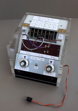
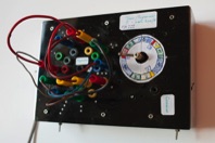
Timer 1
Timer 2
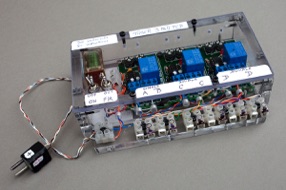
Timer 3 PCB based
Timer 4
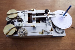
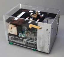
Hommage to Henry machine
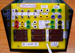
NSEW ch version 2
New Sine Wave machine
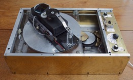
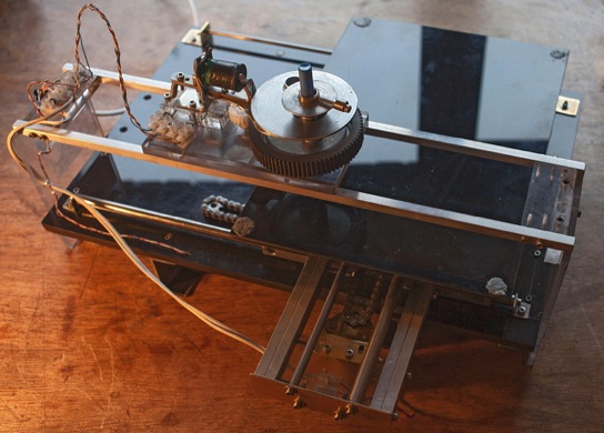
The Hommage to Henry machine is a tribute to Desmond Paul Henry who pioneered drawing machines in the 60's made from a WW2 Bombsight computer. His time in Manchester overlapped with mine but we never met. With the support of his daughter Elaine I reverse engineered a machine to mimic his drawings . The first machine was successful and led me to modify others to make the current one which has an added pen lift mechanism and an elliptical turntable as opposed to a circular one.
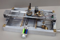
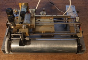
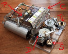
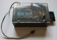
The NSEW Ch machine is an X:Y plotter design. NSEW stands for North, South, East ,West which refer to Cartesian co-ordinates. The prefix 'ch' indicates a chain return mechanism on the axes. The NSEW sp prefix below refers to the sun and planet drives to the axes. The NSEW machines are able to draw with light pens into a digital camera.
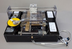
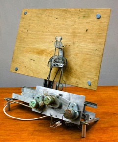
The new Sine Wave machine has a longer drum than the original enabling it to make A3 drawings as opposed to A4 on the original. Other machines are planned.
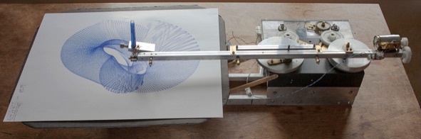
The seven machines and timers were gifted to the Science Museum at the suggestion of the CAS when I was about to move house. Since then I have made replacements. The Linkogram and Meccanograph create Lissajous figures. The Linkogram make similar drawings to a Harmonograph but does not rely on pendulums, so it is superior in that it does not stop and is able to be programmed to repeat a drawing with some accuracy.
The NSEW and Scribblogram machine are X:Y plotter based. The NSEW ch machines have rotating pen attachments whilst the Scribblogram has, as the name implies, a 'scribble' pen function.
The Timers 1, 2 and 4 are completely analogue in their outputs; Timer 3 used PCB boards to output the sequences but was not very successful. The latest Timer 5 is analogue whilst Timer 6 is digital .
Timers 5 and 6 only work with the NSEW